Advanced 3D Piping-English
1,100.00฿
Advanced 3D Piping
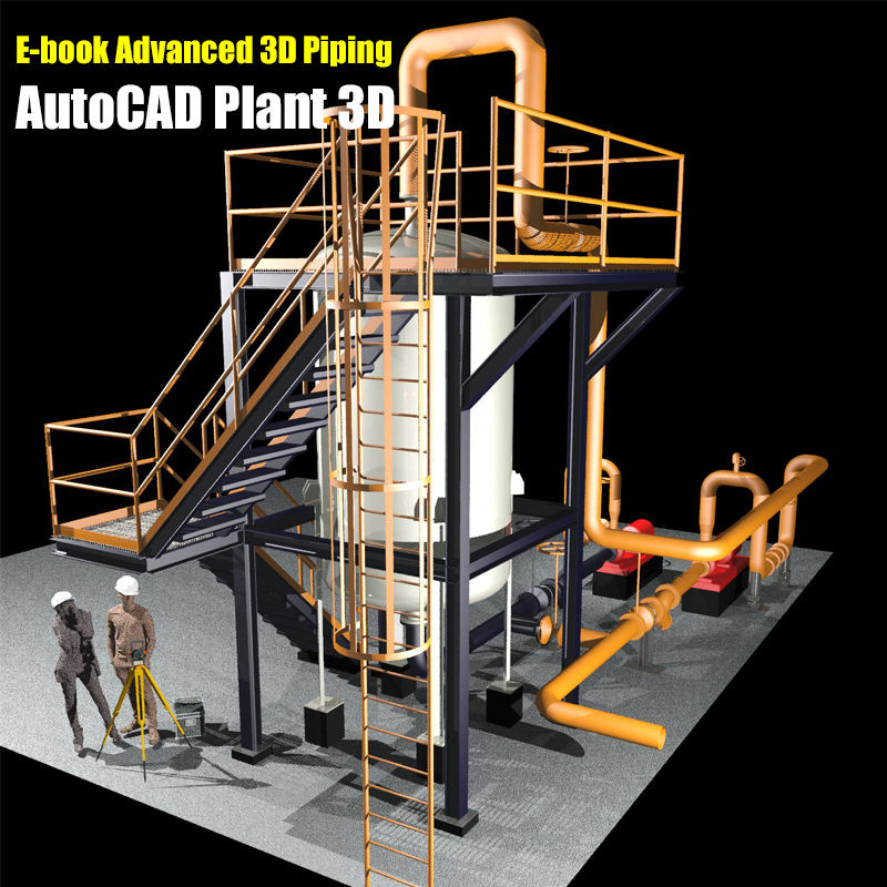
E-book (English) for practicing with the program AutoCAD Plant3D content is suitable for those who have already learned Basic 3D Piping with AutoCAD Plant 3D and would like to extend their knowledge of 3D Piping system management to reduce time and increase 3D Piping efficiency in projects.
E-book the course Advanced 3D Piping
Recommend to buy the course AutoCAD Plant 3D too, if you without experience of 3D Piping
This course is suitable for
- People who have already used or trained AutoCAD Plant 3D
- People who want to be a project admin
- People who want to create Pipe spec standards in their projects
- People who want to customize Project setup to meet project needs.
- Those who want to manage And control all the files in the project
Lesson content
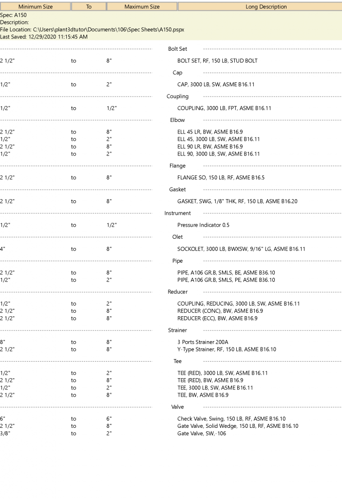
Create New Pipe spec
Pipe spec is a regulated document. The use of all pipe components in the project This document contains requirements that are directly related to P&ID to be applied to 3D piping as well, as well as theBOM. Isometric Piping
All to be specified in Piping Spec the first is the smallest pipe boundary. Up to the largest size That is used in projects, including Fitting types, which identify the code And material of pipes to be used in the project Including devices such as Valve, Bolt Nut, Gasket.
The second part is the Branch table. It is very important in the AutoCAD Plant 3D program where the program canpipe and put Fittings automatically. Caused by creating a pipe specification in the Branch table, which defines the Header and Branch of the pipe used in the project. For this reason The program can run in AutoRoute,
and for specialized equipment. That are not used in the program The author will use the Custom parts and Block mapping process to add them to Pipe spec
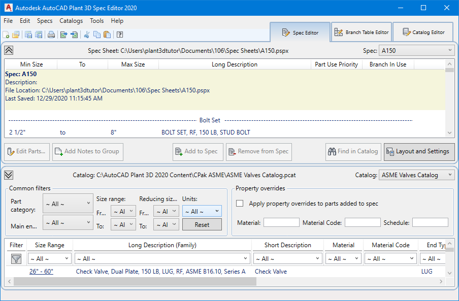
Piping component
This chapter learns how to search for devices from various categories in the ASME Pipe and Fitting Catalog, other than the pipes made in the first chapter. Filters are mainly used in the Catalog panel. The equipment will be divided into 2 classes, the first group is Small bore size from Ø 0.5-2.0 Inch and Mainline Piping size from Ø 2.5-8.0 Inch
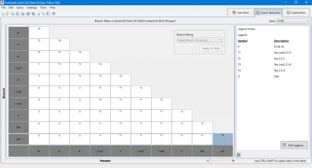
Branch table
Branch table is part of the Header and Branch management in Piping spec how they must be connected. For example, Header 8.0 “is connected to pipe 6.0”, the connection is defined as Tee Reducing 8×6, but if Mainline 8.0 “is connected to pipe 0.5”, the connection is Stub in or use Olet 0.5 “, etc. If the Pipe spec does not create a Branch table All connections are set to Stub in.
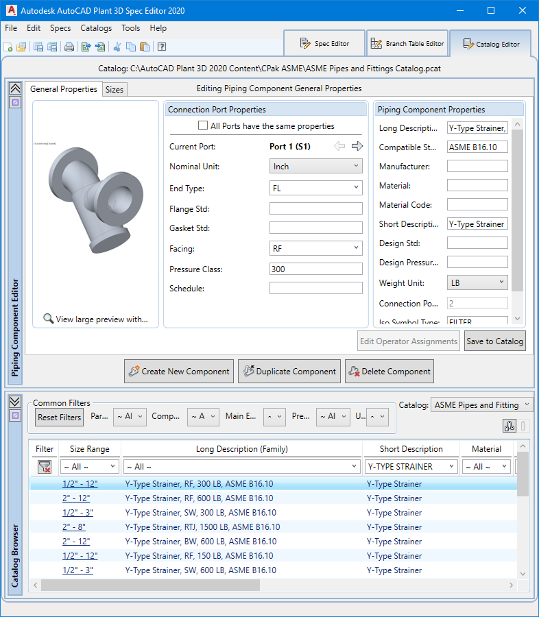
Catalog Editor
Catalog editor window The main function is to manage the Catalog that will be applied to the Pipe spec in the project, which is divided into 2 main parts are The catalog selection section at the bottom, the top part is the Part Properties window and part size configuration in the program that should be checked the most. Equipment installed in pipes such as Valve and Strainer etc. (inline item) Most of the users who use this program will understand that valve and strainer type devices are of the correct dimensions according to the manufacturer’s standards. But the truth is just a dummy model or model that has been assumed only. If used in Pipe spec, it will have a problem that Why is the pipeline real? Within a mismatch, the reason is that the Model valve is not based on the actual size. This chapter teaches you how to do basic management by duplicating devices from that Catalog to customize. Then apply to Piping spec
Block mapping
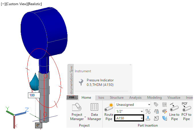
In this chapter, the author will teach you how to create Isometric symbols and then Mapping with the Parametric part in the catalog by using Pressure gauge 0.5 “from the previous chapter to mapping with the Isometric symbol that has been created. After finishing the step, 250-ANGLE VALVE, a 3D model, will be taken into the process of Plant part convert and reverse the process of Block mapping and custom part again and then bring that part to work in the Project
Custom part
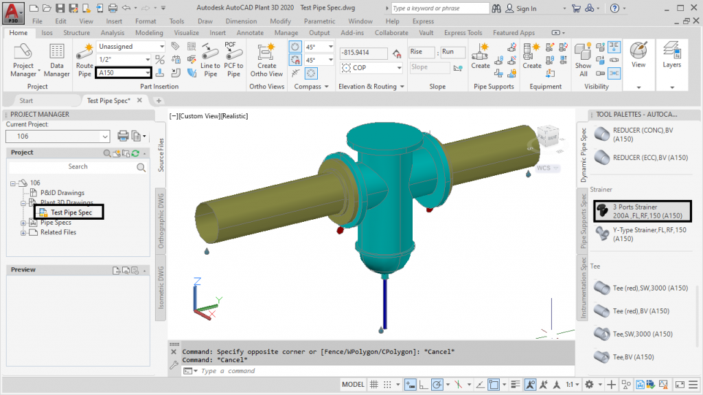
This Custom Part is an example of creating a strainer with three connection points (3 Ports) from a pre-built model, which will set the left and right ports equal to 8 “and the bottom part is set to 0.5”. Spec Editor can create a maximum of 4 Ports

Project Setup General Setting
In this chapter, you will learn how to modify important parts of Project Setup General Setting in the areas that are required in the project. For example, adding a tag to the library, creating a drawing properties and file name format, adding a List Pipe spec to the system, and creating different attributes to be used in a project
Data Manager
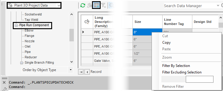
is a search engine. And manage data in the project Able to choose to manage data both only for files Or aggregate data of the entire project.At this stage, files from other projects will be imported to override Pipe spec and Line number and Re-Assign Equipment Tag again, then data will be collected in the Pipeline and Equipment Tag think Export to Excel to update, then Import into the project again to update
Plant 3D Drawing Setting
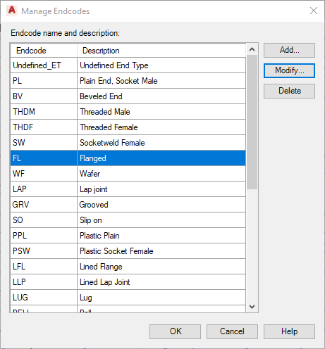
This chapter will learn to adjust the properties necessary for piping 3D operation, adjusting the color of the pipes shown in Piping 3D, managing the connections of pipes and valves (Piping. Connection Setting), as well as handling 3D Pipe line Number to provide information accurately. To customize the Isometric Pipe line number tag display by editing Iso Configuration in the program
Isometric Publish
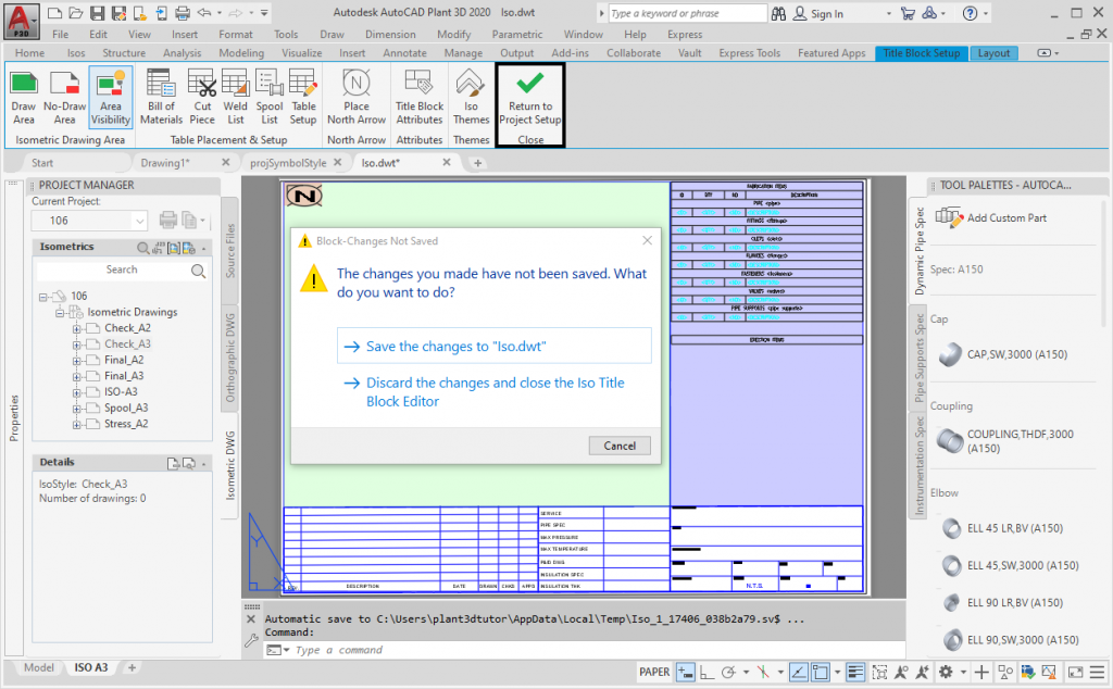
In this section, you will learn how to set up an Isometric piping template, which is an extension of the first Basic 3D Piping manual to illustrate the isometric piping requirements. Or determining the distance of the welding point to be shown in the form Or a special message To be added, etc. Including setting the Print Isometric Drawing after Generate to DWG. You can print out PDFs all at once with AutoCAD’s Publish command, which must be set to Publish first. This chapter explains the steps. All
Custom Orthographic
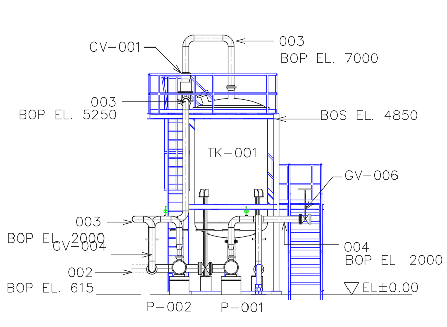
Orthographic is a tool for creating projections in AutoCAD Plant 3D, which can bring the designed 3D model piping to a different perspective. Including creating a Section image, Dimension in the form of calling the Tag displayed in the Update all information. Including transcribing of materials in Piping 3D, and in this lesson we will add a drawing template method by setting the Title block to A3 size and creating automation (Field) to reduce review time, edit and manage layer and attribute. That must be displayed
Sheet set Manager.
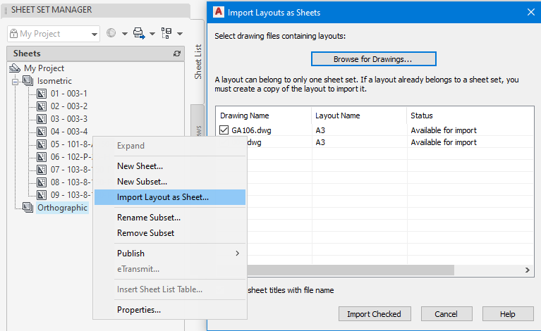
Sheet set manager is a management tool. And edit the order in the project To prepare to deliver all work drawings And can also bring other .DWG files to manage in the project as well You can edit the file name and create additional attributes from this window. You can publish and eTransmit all files of this project from this window as well.
| Color | Monochrome, 4 Color |
|---|
You must be logged in to post a review.
สินค้าที่เกี่ยวข้อง
-

-

SolidWorks Electrical 2018
ให้คะแนน 0 ตั้งแต่ 1-5 คะแนน850.00฿ – 950.00฿เลือกรูปแบบ This product has multiple variants. The options may be chosen on the product page -
-
Navisworks
ให้คะแนน 0 ตั้งแต่ 1-5 คะแนน500.00฿เลือกรูปแบบ This product has multiple variants. The options may be chosen on the product page

รีวิว
ยังไม่มีบทวิจารณ์