
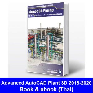
Advanced 3D Piping-English
1,100.00฿
Advanced 3D Piping
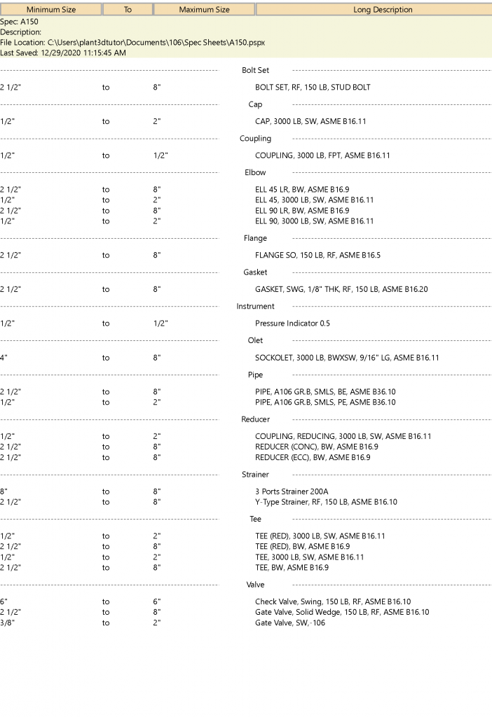
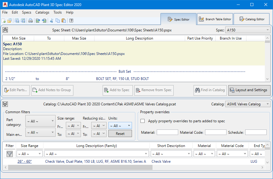
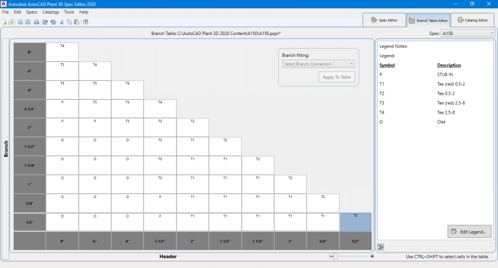
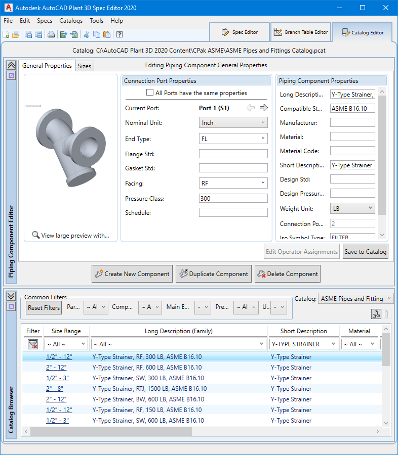
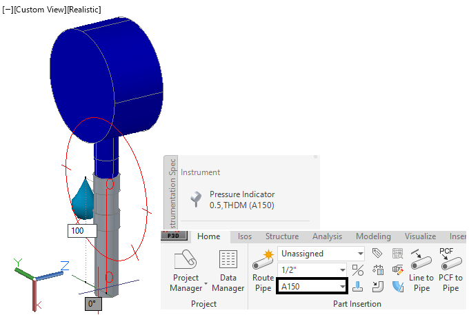
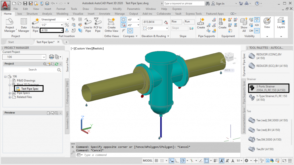
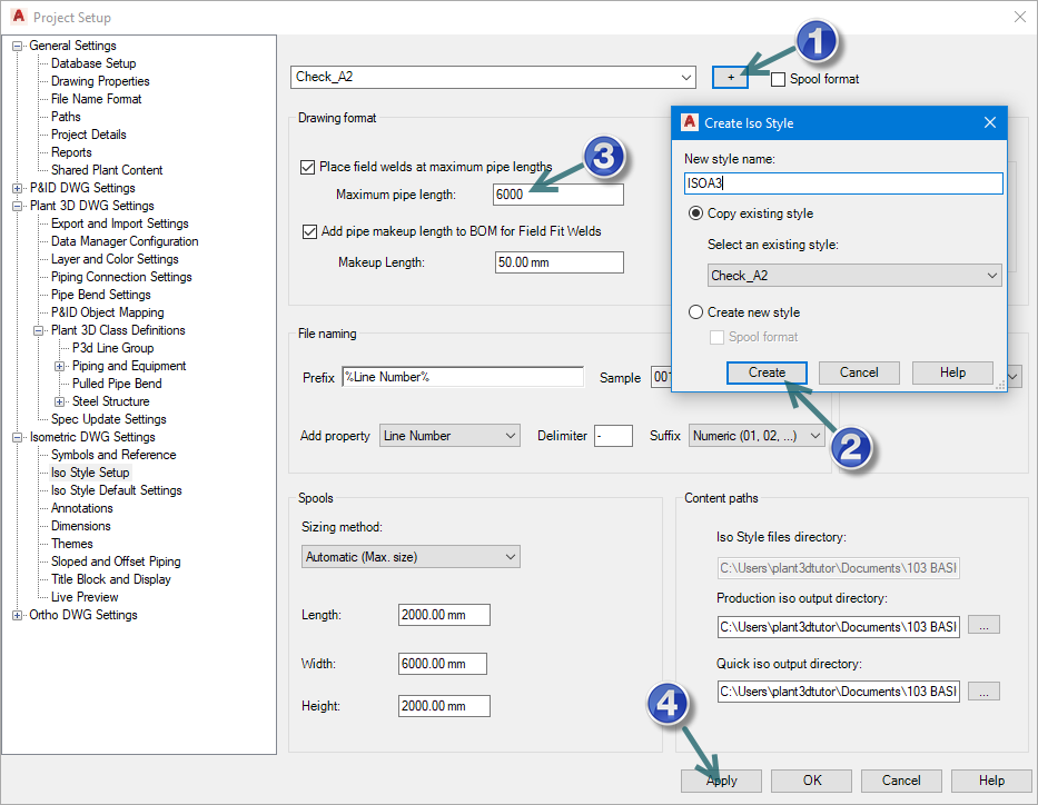
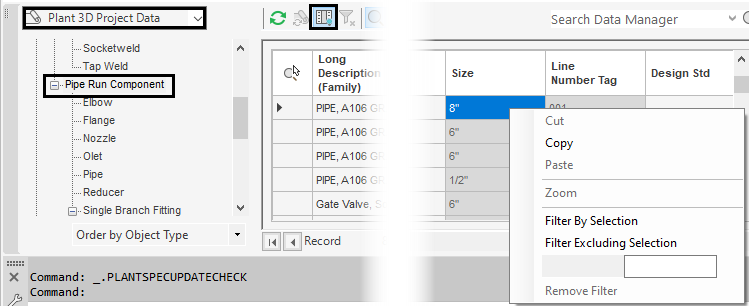
E-book (English) for practicing with the program AutoCAD Plant3D content is suitable for those who have already learned Basic 3D Piping with AutoCAD Plant 3D and would like to extend their knowledge of 3D Piping system management to reduce time and increase 3D Piping efficiency in projects.

รีวิว
ยังไม่มีบทวิจารณ์